
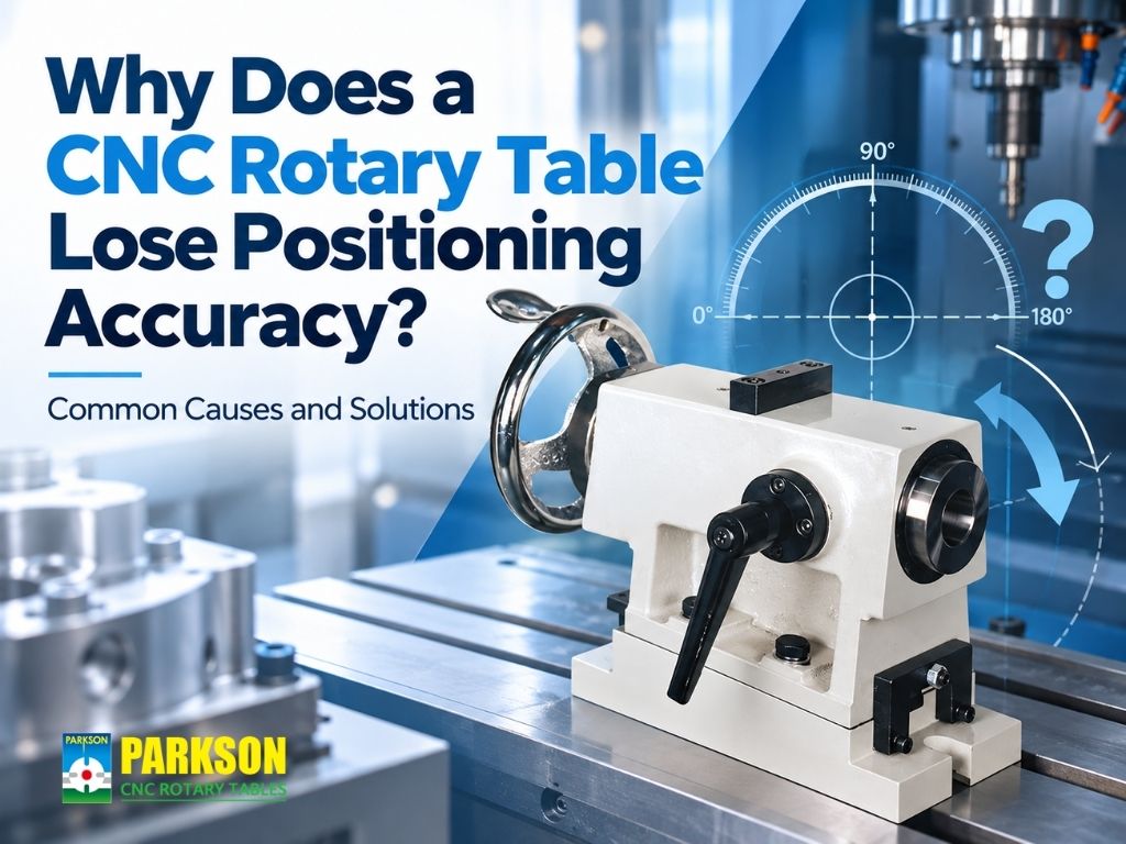
A CNC rotary table can lose positioning accuracy due to mechanical backlash, transmission wear, insufficient clamping rigidity, servo control problems, thermal expansion, or rotary-axis misalignment. However, inaccurate machined parts do not necessarily mean the rotary table itself is defective.
The first step is to identify when the error occurs. Does the position change after the axis reverses direction? Does accuracy deteriorate under heavy cutting loads? Or do dimensional errors increase as the machine warms up?
These symptoms can point to different causes and require different corrective actions.
This guide explains how to identify common CNC rotary table accuracy problems, distinguish positioning errors from repeatability issues, and determine when calibration, maintenance, or equipment upgrades should be considered.
1. Quick Diagnosis: What Is Causing Your Rotary Table Accuracy Problem?
The fastest way to investigate a CNC rotary table positioning error is to identify the conditions under which it appears. Direction-dependent errors, load-related movement, and temperature-related drift often indicate different problems.
Use the following table to narrow down the possible causes before adjusting machine parameters or replacing components.
| Observed Problem | Possible Cause | What to Check First |
|---|---|---|
| Position changes after direction reversal | Backlash or directional lost motion | Compare clockwise and counterclockwise positioning |
| Accuracy is acceptable without cutting but poor under load | Insufficient clamping or structural rigidity | Inspect workholding, clamping, and cutting forces |
| Positioning errors increase during long machining cycles | Thermal expansion | Compare cold and warm operating conditions |
| Repeated positioning results vary | Servo response, feedback instability, or fixture movement | Perform controlled repeatability tests |
| Features on different machining faces do not align | Rotary-axis alignment or coordinate errors | Verify axis geometry and work offsets |
| Unusual noise occurs with accuracy loss | Transmission, bearing, or lubrication problems | Inspect mechanical condition and lubrication |
Important: These symptoms indicate where to begin troubleshooting, not a confirmed diagnosis. Multiple factors can produce similar machining errors.
2. What Does CNC Rotary Table Accuracy Actually Mean?
CNC rotary table accuracy describes how closely the rotary axis reaches its commanded angular position. However, accurate machining also depends on repeatability, backlash, clamping stability, and machine alignment.
These factors should be evaluated separately because they produce different error patterns.
Positioning Accuracy
Positioning accuracy describes the difference between the commanded angular position and the actual position reached.
For example, if a rotary axis is commanded to move to 90°, any deviation from that target contributes to positioning error.
A consistent positioning offset may indicate a reference-setting, calibration, or geometric alignment issue.
Repeatability
Repeatability describes how consistently the rotary axis returns to the same position under specified operating conditions.
A rotary table can have good repeatability but still have a systematic positioning error. This is why repeated measurements at a single angle cannot fully establish overall positioning accuracy.
Backlash and Lost Motion
Backlash is associated with clearance in mechanical transmission components. It may become noticeable when the rotary axis reverses direction.
However, direction-dependent positioning differences can also arise from other sources, including elastic deformation or control behavior.
Key distinction: Positioning accuracy determines how close the axis reaches its target, while repeatability determines how consistently it returns. Both matter for precision CNC machining.
3. Six Common Causes of CNC Rotary Table Accuracy Problems
Rotary table positioning errors may originate from mechanical components, machine control, workholding, or environmental conditions. Understanding how each factor affects machining results helps manufacturers avoid unnecessary adjustments.
Cause 1: Mechanical Backlash and Transmission Wear
Mechanical backlash can cause directional positioning differences when a rotary axis reverses movement. This is particularly relevant to rotary tables using worm gear or other mechanical transmission systems.
As transmission components operate over time, clearance, wear, or incorrect adjustment may affect motion transfer between the motor and rotary axis.
A typical symptom is a repeatable difference when approaching the same programmed angle from opposite directions.
How to verify: Measure the actual position at a selected angle after approaching it clockwise and counterclockwise. Compare the results under consistent conditions.
Recommended action: Inspect the transmission and relevant compensation settings according to the manufacturer's service procedures. Mechanical wear should be corrected at its source rather than concealed through excessive compensation.
For applications requiring minimal mechanical transmission backlash, PARKSON's Direct-Drive High Speed Rotary Table range provides an alternative using torque motor technology.
Direct-drive construction eliminates backlash associated with intermediate gear transmission, although overall accuracy still depends on feedback, structural stability, and machine integration.
Cause 2: Insufficient Clamping Rigidity or Fixture Movement
A rotary table may reach the correct angle but fail to maintain the required workpiece position during cutting. In this situation, the problem may involve clamping or structural rigidity rather than angular positioning accuracy.
Heavy milling, interrupted cutting, long tool overhangs, and large workpieces can generate substantial cutting forces and overturning moments.
If the fixture, workpiece clamping, or rotary table structure cannot adequately resist these forces, movement or deflection may affect the finished dimensions.
How to verify: Compare machining results under light and heavy cutting conditions. Inspect the workholding setup and determine whether errors increase with cutting load.
Recommended action: Review fixture mounting, workpiece clamping, rotary table mounting, and applicable hydraulic or pneumatic clamping conditions.
Manufacturers should also consider the combined weight of the workpiece and fixture, the center of gravity, and the cutting forces involved.
Rated load capacity alone does not guarantee sufficient rigidity for every machining application.
Cause 3: Encoder Feedback or Servo Control Problems
Servo control or feedback problems can affect how accurately and consistently a CNC rotary table reaches its programmed position.
Depending on the system configuration, rotary-axis feedback may come from a motor encoder or a measuring device installed closer to the rotary axis.
Incorrect servo parameters, reference-setting errors, feedback signal problems, or unsuitable control settings may contribute to unstable positioning.
Possible symptoms include overshoot, oscillation, inconsistent settling, or abnormal behavior during acceleration and deceleration.
How to verify: Review CNC alarms, servo diagnostics, reference positions, and repeatability measurements. Qualified technicians should inspect feedback operation and control parameters.
Recommended action: Verify the feedback system and servo configuration according to the CNC and drive manufacturer's procedures.
A higher-resolution encoder does not automatically correct mechanical deflection, backlash outside the measured feedback path, or inaccurate machine geometry.
Cause 4: Thermal Expansion During Extended Machining
Thermal changes can cause machining accuracy to drift even when the rotary axis continues to follow its programmed commands.
Heat generated by motors, bearings, transmission components, cutting operations, and the surrounding environment can affect machine geometry.
As temperatures change, the relative positions of the rotary axis, workpiece, and cutting tool may also change.
This can become noticeable during long production runs or when machining parts with tight dimensional tolerances.
How to verify: Compare measurements shortly after startup and after the machine reaches a more stable operating temperature.
Recommended action: Follow the machine builder's warm-up procedures, inspect temperature-related trends, and verify applicable thermal compensation settings.
If the error changes with temperature, evaluate the entire machining system before assuming that the rotary table alone is responsible.
Cause 5: Rotary-Axis Alignment and Calibration Errors
Incorrect rotary-axis alignment can produce machining errors across multiple workpiece faces even when angular positioning itself is repeatable.
In four-axis and five-axis machining, the CNC controller must correctly relate rotary movement to the machine's linear axes.
Errors in the rotary-axis centerline, pivot parameters, work offsets, or coordinate transformations may cause the programmed toolpath to differ from the actual workpiece geometry.
A typical symptom is a part that machines correctly on one face but develops feature-location errors after rotation.
How to verify: Check the rotary-axis alignment, reference position, work offsets, and relevant machine kinematic parameters.
Recommended action: Perform calibration using suitable measurement equipment and procedures specified by the CNC machine builder.
Repeatedly adjusting individual work offsets may temporarily improve a part but can leave the underlying geometric problem unresolved.
Cause 6: Lubrication Problems, Contamination, and Component Wear
Insufficient lubrication, contamination, or deterioration of mechanical components can affect rotary motion consistency and long-term performance.
Depending on the rotary table design, lubrication problems or damaged bearings and transmission components may increase friction, operating temperature, or mechanical resistance.
Warning signs can include unusual noise, temperature changes, leakage, inconsistent movement, or progressively worsening positioning results.
How to verify: Inspect lubrication condition, seals, bearings, and transmission components according to the applicable maintenance procedures.
Recommended action: Follow the manufacturer's lubrication and inspection requirements. Arrange qualified service if abnormal resistance, noise, or mechanical movement is detected.
Maintenance requirements differ between conventional gear-driven and direct-drive rotary table designs.
For additional preventive maintenance information, read Tilting Rotary Table Maintenance Guide: Lubrication, Calibration, and Service Life.
4. How to Troubleshoot CNC Rotary Table Positioning Errors
An effective rotary table troubleshooting process should isolate one possible cause at a time. Changing multiple parameters simultaneously makes it difficult to determine which adjustment corrected the problem.
The following procedure provides a practical starting point for identifying positioning-related errors.
Step 1: Establish a Reliable Reference Measurement
Select a defined rotary position and use a suitable measuring method to record the commanded and actual angular positions.
The measuring equipment should be appropriate for the required tolerance. For high-precision applications, qualified technicians may use calibrated rotary measurement systems and relevant machine-tool verification procedures.
Step 2: Compare Clockwise and Counterclockwise Positioning
Approach the same programmed angle from both directions and compare the results.
A consistent difference may indicate backlash, directional lost motion, or control-related behavior.
Step 3: Compare Unloaded and Cutting Conditions
Check positioning performance without cutting, then compare it with the results obtained under normal machining loads.
If errors appear mainly during cutting, investigate fixture movement, clamping stability, structural deflection, and cutting forces.
Step 4: Check Thermal Stability
Repeat measurements under comparable cold and warm operating conditions.
A gradual change may indicate temperature-related effects rather than an immediate mechanical positioning failure.
Step 5: Verify Machine Geometry and Control Settings
If the error persists, qualified technicians should review rotary-axis alignment, reference settings, encoder feedback, servo parameters, and mechanical condition.
Step 6: Confirm the Result After Correction
Repeat the original measurement under the conditions that produced the error.
For example, if the problem occurred after direction reversal, verify both approach directions. If it occurred during heavy cutting, confirm performance under representative machining loads.
Key takeaway: The goal is not simply to produce one acceptable test part. It is to establish stable and repeatable performance under actual production conditions.
5. When Should You Repair, Calibrate, or Upgrade?
The correct response to a CNC rotary table accuracy problem depends on its confirmed cause. Calibration may resolve a reference or alignment issue, while worn mechanical components may require service or replacement.
An equipment upgrade becomes worth considering when the existing rotary table can no longer meet the application's required accuracy, load, motion, or production demands.
| Confirmed Problem | Recommended Action |
|---|---|
| Consistent positioning offset | Verify reference settings and calibration |
| Direction-dependent backlash or lost motion | Inspect transmission and applicable compensation |
| Movement under cutting loads | Improve workholding or evaluate rigidity and clamping |
| Thermal drift | Review warm-up procedures and thermal stability |
| Mechanical wear or abnormal noise | Arrange inspection and component service |
| Existing rotary system cannot meet required motion performance | Evaluate a more suitable rotary table configuration |
Should You Upgrade to a Direct-Drive Rotary Table?
Direct-drive technology may be worth considering when the application requires high rotary response, frequent direction changes, or coordinated multi-axis machining.
Unlike conventional gear-driven designs, direct-drive rotary tables use torque motors without intermediate gear transmission.
This removes gear transmission backlash and can reduce wear associated with those components.
However, direct-drive technology is not automatically the best solution for every application. Conventional rotary tables may remain suitable for indexing, heavy-duty positioning, and other machining requirements.
Manufacturers should compare the required accuracy, load, rigidity, rotary motion, and control integration before selecting a replacement system.
For a more detailed comparison, see The Evolution of CNC Rotary Tables: From Worm Gear Drive to Direct-Drive Systems.
6. PARKSON CNC Rotary Table Solutions for Precision Machining
PARKSON provides CNC rotary table solutions for different indexing, positioning, and multi-axis machining requirements.
Its product lineup includes conventional CNC rotary tables, horizontal rotary tables, tilting rotary tables, and direct-drive high-speed rotary tables.
When evaluating an accuracy problem, manufacturers should first determine whether the existing equipment requires calibration or maintenance, or whether its capabilities no longer match the machining application.
CNC Rotary Tables for Positioning and Multi-Face Machining
PARKSON's CNC rotary table products support applications requiring controlled workpiece rotation and angular positioning.
Important selection considerations include workpiece and fixture load, rotary-axis configuration, positioning requirements, clamping, and machine compatibility.
Explore PARKSON CNC Rotary Table Products →
Direct-Drive Rotary Tables for Advanced Rotary Motion
PARKSON's Direct-Drive High Speed Rotary Table product range includes fourth-axis and fourth-/fifth-axis configurations.
The series uses torque motor technology and supports different rotary machining requirements, including indexing and continuous rotary motion.
For example, the HMCD Series features a direct-drive motor design without intermediate gear transmission and offers optional encoder configurations.
These features may be relevant for manufacturers evaluating low-backlash rotary motion and responsive axis control.
However, the final machining result still depends on machine installation, feedback configuration, workholding, structural stability, and CNC integration.
Information to Prepare Before Requesting Technical Support
To help evaluate rotary table accuracy requirements, manufacturers should prepare the CNC machine model, rotary table model, workpiece dimensions, fixture weight, cutting conditions, and observed error pattern.
Positioning measurements are particularly useful when they show whether the error occurs after direction reversal, during heavy cutting, or after extended operation.
Providing these details can help distinguish a maintenance or calibration issue from an application requiring a different rotary table configuration.
7. Frequently Asked Questions
Can a CNC rotary table have good repeatability but poor positioning accuracy?
Yes. A rotary table may consistently return to nearly the same angular position while that position differs from the programmed target.
This indicates that repeatability and absolute positioning accuracy should be evaluated separately. A systematic positioning offset may require reference verification or calibration rather than mechanical component replacement.
Why does rotary table accuracy change after reversing direction?
Direction-dependent errors may result from mechanical backlash, transmission wear, elastic deformation, or servo control behavior.
Comparing the actual position when approaching the same target angle from opposite directions can help identify the pattern. Additional inspection may be required to determine the cause.
Will a direct-drive rotary table eliminate all positioning errors?
No. Direct-drive technology eliminates backlash associated with intermediate mechanical gear transmission, but other sources of error remain.
Encoder feedback, thermal expansion, machine alignment, structural deflection, clamping stability, and CNC control configuration can still affect positioning accuracy and final machining results.
Conclusion: Identify the Cause Before Replacing the Rotary Table
When a CNC rotary table produces inconsistent machining results, the most effective solution begins with identifying the actual source of the error.
Mechanical backlash, insufficient clamping rigidity, servo feedback problems, thermal changes, axis misalignment, and component wear can produce different positioning symptoms.
A systematic troubleshooting process helps manufacturers distinguish these causes, avoid unnecessary adjustments, and determine whether calibration, maintenance, or equipment replacement is appropriate.
The goal is not simply to restore one correct angular position, but to maintain reliable machining accuracy under real production conditions.
Improve CNC Rotary Table Performance with PARKSON
Are positioning errors, unstable rotary motion, or changing machining requirements affecting your CNC production?
PARKSON provides CNC rotary table solutions for indexing, precision machining, and multi-axis applications.
Whether you are evaluating a conventional rotary table or considering direct-drive technology, sharing your machining requirements and accuracy challenges can help identify a suitable equipment configuration.